سیم خاردار

حصار کشی تجربه های یک مهندس برق!

سیم خاردار

حصار کشی تجربه های یک مهندس برق!

۳ مطلب با کلمه‌ی کلیدی «smps» ثبت شده است

  • ۰
  • ۰

Diodes Characteristics

فک میکردم که دیود دیگه داستان نداره و همین یه زمان روشن شدن و جریان و دراپ و جریان نشتی و ایناس فقط که یهو فهمیدم یه جا یه دیود اسنابر بعلت "جریان ریورس ریکاوری" میسوزه!!که رسیدیم به این داستان ها:
خب دیود های غیر شاتکی ساختارشون این مدلیه:

diode1

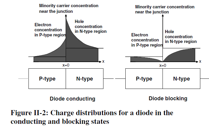
یعنی برای این که روشن بشن حامل های جریان(الکترون ها و حفره ها) میان دور مرز ناحیه pn جمع میشن.این باعث میشه زمانی که سر روشن کردن و خاموش کردن یه جریانی صرف تغییر وضعیت این حامل ها بشن که توی زمان خاموش شدن به اصطلاح جریان ریورس ریکاوری نامیده میشه و اگه یه موقع بخوایم با زور دیود رو خاموش کنیم باعث ایجاد مقداری تلفات میشه.

diode2diode3

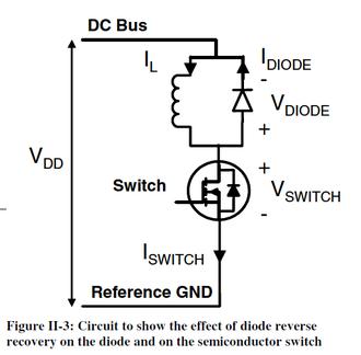
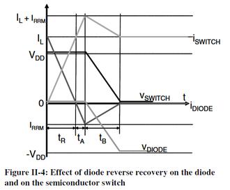
بعنوان مثال این مدار سمت راست رو در نظر بگیرید زمانی که ما سوییچ رو روشن میکنیم خب در واقع دیود رو خاموش میکنم و نمودار جریان و ولتاژ بالا (زمان صفر زمانی هس که ولتاژ گیت از ولتاژ تریشلد رد شده و روبه زیاد شدن هس). اون اور کارنتی که جریان سوییچ نسبت به جریان کاریش داره لحظه ای که میرسه به جریان کاریش، بخاطر وجود دیود هست و در واقع بخاطر جریان ریورس ریکاوری دیود.نتیجتا جریان ریورس ریکاوری باعث بیشتر شدن تلفات سوییچ میشه که توی طراحی باید در نظر گرفته بشه. اون پیک جریان ریورس دیود Irr نامیده میشه که توی دیتاشیت هم میاد و بعضا میتونه از جریان نامی دیود هم بیشتر بشه! این جریان Irr با افزایش دما یا افزایش di/dt و یا افزایش خود جریان کاری، افزایش پیدا میکنه.(همچنین زمان ریورس ریکاوری هم با افزایش دما افزایش پیدا میکنه.جالبه بدونید راپ دیود با افزایش دما کاهش پیدا میکنه)

خب به ترتیب تلفات روشن شدن دیود، روشن شدن ماسفت زمانی که دیود هم هست تو مدار، و زمانی که دیود نیست تو مدار، تلفات اضافی سوییچ که بخاطر وجود دیود هست، اخری هم یه شکل دیگه از فرمول تلفات سوییچ زمانی که دیود نیست.

diodedissiption
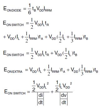
اگه توی فرمول تلافت اضافی ناشی از دیود نگاه کنید میبینید توی زمان ta یه جریان باعث اتلاف میشه و توی زمان tb یه جریان دیگه(کمتر و مساوی جریان زمان قبلی) باعث وجود تلاف میشن.توی دیود های فست tb خیلی کمتر از ta میشه که در نتیجه برای یه زمان ریورس ریکاوری ثابت دیود فست تلفات مسیر مدار رو بیشتر میکنه اما تلفات روشن شدن دیود که همون معادله اول هست کم میشه.

خب لازم به ذکره که بگم با افزایش جریان نامی دیود جریان ریورس ریکاوری زیاد میشه و با زیاد شدن ولتاژش جریان ریورس ریکاوری کم میشه!
البته خب این برای دیود های سریع تر تاثیرش کم میشه و همون طور که گفتم افزایش دما تاثیر خیلی بیشتری روش داره تا این پارامترها...
و گفتیم هم که با افزایش di/dt هم زمان و هم جریان ریورس ریکاوری زیاد میشن در حالی که تلفات ماسفت کم میشن...اصن اوضاعیه ...
اینم خلاصه این مقاله ای که بیشتر ازش استفاده کردم:

CONCLUSION
Reverse recovery in diodes introduces small
losses in the diode but larger losses in the MOSFET
or IGBT which is switching the diode. These losses
are influenced by the two reverse recovery
parameters IRRM and tRR.
From a system design perspective, there are three
aspects influencing the optimization of a half-bridge
structure: di/dt, diode choice and the possible
inclusion of a parallel capacitor.
Higher di/dt results in lower EON losses in the
circuits tested, noting that higher di/dt increases
IRRM losses less than it decreases the normal
switching losses. So from perspective of switch and
diode losses, increasing di/dt is beneficial despite
the increase in IRRM.
The use of fast recovery diodes improves
switching losses, but generally worsens conduction
losses. Larger current rated diodes of the same
family have higher IRRM resulting in higher EON, and
a larger capacitance, resulting in lower EOFF. Overdimensioning
of the diodes is not recommended as
this leads to higher total switching losses.
Addition of extra capacitance increases EON losses
but decreases EOFF losses. There is the possibility
that an optimum total loss point will exist, meaning
that the addition of extra capacitance will reduce
total losses. Designers of circuits using half-bridges
should consider this possibility in their applications:
inclusion of a low cost capacitor may help improve
efficiency.

اینم یه عکس خلاصه از مقایسه دیود های با ساختار متفاوت:
defferents of diodes

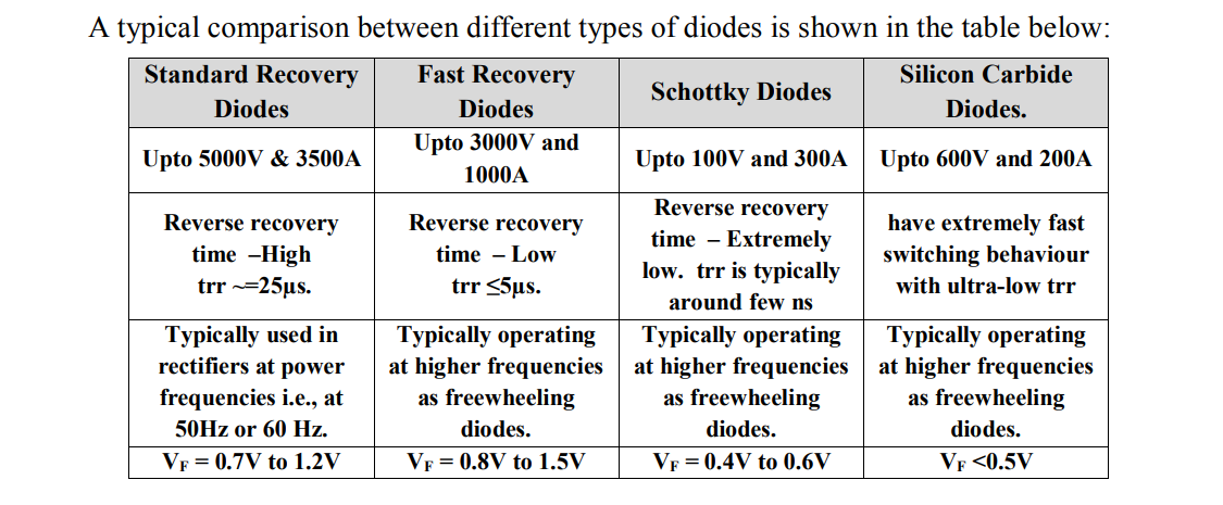
باشد که رستگار شویم...:)

  • Mohammad Hassani
  • ۰
  • ۰

یه قسمت از کتاب پرسمن
واقعا لذت بخش بود.چسبید.حیفم اومد از خودم بنویسم، کپی کردم.
یه مقایسه از معایب و مزایای هر یک:

The two modes have significantly different operating properties
and usages. The discontinuous mode, which does not have a
right-half-plane-zero in the transfer function, responds more rapidly
to transient load changes with a lower transient output voltage
spike.
A penalty is paid for this performance, in that the secondary peak
current in the discontinuousmodecan be between two and three times
greater than that in the continuous mode. This is shown in Figures
4.2b and 4.2d. Secondary DC load current is the average of the current
waveshapes in those figures. Also, assuming closely equal “off” times,
it is obvious that the triangle in the discontinuous mode must have a
much larger peak than the trapezoid of the continuous mode for the
two waveshapes to have equal average values.
With larger peak secondary currents, the discontinuous mode has
a larger transient output voltage spike at the instant of turn “off”
(Section 4.3.4.1) and requires a larger LC spike filter to remove it.
Chapter 4: Flyback Converter Topologies 129
Also, the larger secondary peak current at the start of turn “off” in the
discontinuous mode causes a greater RFI problem. Even for moderate
output powers, the very large initial spike of secondary current at
the instant of turn “off” causes a much more severe noise spike on
the output ground bus, because of the large di/dt into the output bus
inductance.
After Pressman A major advantage of the discontinuous mode is that
the secondary rectifier diodes turn “off” under low current stress conditions.
Also they are fully “off” before the next “on” edge of Q1. Hence the problem
of diode reverse recovery is eliminated. This is a major advantage in high
voltage applications as diode reverse recovery current spikes are difficult to
eliminate and are a rich source of RFI. ∼K.B.
Due to the poor form factor, secondary RMS currents in the discontinuous
mode can be much larger than those in the continuous
mode. Hence, the discontinuous mode requires larger secondary wire
size and output filter capacitors with larger ripple current ratings.
The rectifier diodes will also run hotter in the discontinuous mode
because of the larger secondary RMS currents. Further, the primary
peak currents in the discontinuous mode are larger than those in the
continuous mode. For the same output power, the triangle of Figure
4.2a must have a larger peak than the trapezoid of Figure 4.2c. The
consequence is that the discontinuous mode with its larger peak primary
current requires a power transistor of higher current rating and
possibly higher cost. Also, the higher primary current at the turn “off”
edge of Q1 results in a potential for greater RFI problems.
Despite all the disadvantages of the discontinuous mode, it is much
more widely used than the continuous mode. This is so for two reasons.
First, as mentioned above, the discontinuous mode, with an inherently
smaller transformer magnetizing inductance, responds more
quickly and with a lower transient output voltage spike to rapid
changes in output load current or input voltage. Second, because of a
unique characteristic of the continuous mode (its transfer function has
a right-half-plane-zero, to be discussed in a later chapter on feedback
loop stabilization), the error amplifier bandwidth must be drastically
reduced to stabilize the feedback loop.
After Pressman Modern power devices, such as the Power Integration’s
Top Switch range of products, have the “noisy” FET drain part of the chip
isolated from the heat sink tab. This, together with integrated drive and
control circuits, which further reduce radiating area, very much reduces the
RFI problems normally associated with the discontinuous flyback topology.
∼K.B.

  • Mohammad Hassani
  • ۰
  • ۰

سلام
تو این پست سعی میکنم که smps و سورس های مناسبش رو در وهله ی اول معرفی کنیم و در پست های بعد جزئی تر هر بخشش رو و همچنین سورس های مربوطه رو بذارم.
منبع تغذیه موضوع واقعا پیچیده ای هست و اصلا کاره یکی دو روز نیست و اگه که دارید شروع میکنید توصیه میکنم که حتما با حوصله برید سورس های اصلی رو که در ادامه معرفی میکنم بخونید.

یه منبع تغذیه رو میشه به بخش های زیر تقسیم کرد:
1-یکسو کننده و خازن (های) بالک
2-بخش سوییچینگ(ها) و درایور سوییچ (ها)
3-ترانس
4-فیلتر خروجی
5-کنترلر
1-6-لاین فیلتر
2-6-مدار های اسنابر سوییچ ها و ...
6-3-پیاده سازی فیدبک و جبران سازی
4-6-نکات مربوط به ایزولاسیون
5-6-نکات مربوط به بحث نویز پذیری و ...
6-6-یادم اومد اضافه میکنم باز

این یه پاورپوینته که توش خیلی مختصر سوییچینگ رو معرفی میکنم:
http://uplod.ir/on6u2to5pedt/smps.pptx.htm
این هم یه پاورپونته که خیلی مختصر منبع هاف بریدج رو بررسی کردم:(حتا اگه هدفتون یاد گیری این مدل منبع تغذیه هم نباشه خودنش مفیده)
http://uplod.ir/f93os08x9xek/halfbeidge.pptx.htm
خب کتابای خوبی که توی این زمینه وجود داره :
cookbook
کتابه switching power supply design که نوشته ی perssman هست و من توصیه میکنم این رو بخونید مفصل هست اما تقریبا کامل و رویکرد عملی هم داره

این هم توضیحات آقای جبرائیلی هست که واقعا وقت گذاشتن و خیلی خوبه:
http://www.eca.ir/forums/thread29492.html
این هم توضیحات آقای b2 هست(اسمشون رو نمیدونم) که راجبه منبع تغذیه فلایبک هست اما در هر حال خوندنش خیلی خوبه
http://www.eca.ir/forums/thread39649.html
این سایت هم توش مطالب خیلی خوبی پیدا میشه و همچنین میتونید انواع منبع تغذیه ی دلخواه رو طراحی کنید که البته کلا ابزارهای طراحی بیشتر بدرد آموزش و تحلیل در راستای یادگیری میخورن:
http://www.poweresim.com/
این یکی هم باز میتونید توش منبع تغذیه طراحی کنید و باز هم از جنبه ی آموزش ارزشمنده:
http://schmidt-walter-schaltnetzteile.de/
یه نرم افزار منبع تغذیه فلایبک هم هس به اسم PIExpert و این هم لینکی که توش خیلی کامل بررسیش کردن:
http://www.eca.ir/forums/thread21882.html
این همه یه خلاصه خیلی مختصر و مفید از انواع توپولوژی ها:
http://www.smps.us/topologies.html

در ادامه بخش های یک منبع تغذیه رو معرفی میکنم و سورس هاشون میذارم.
در ضمن پست ها به مرور ارتقا داده میشن.
راستی اگه اشتباهی دارم متذکر بشید و یا مطلبی برای اضافه کردن(به اسم خودتون) معرفی کنید خوشحال میشم.

  • Mohammad Hassani